United States
Canada
- Europe
Netherlands
Germany
- Africa
- Rest of World
This issue will cover the oil lubricated version of the Tungsten Carbide and Silicon Carbide seal. It is found in some or most Gorman-Rupp T Series (trash), S Series (submersible), PA Series (Prime Aire) and industrial pumps (0 Series, 10 Series, and 80 Series). The content of this bulletin will cover what the seal means, why Gorman-Rupp uses this seal, what can it do for you, and how to replace it. We will provide this and other information to questions in this issue.
Definitions
Tungsten Carbide - This is a material used for the manufacturing of the seal’s faces. Tungsten Carbide is a two part material. Tungsten and Carbide are mixed together and combined with a matrix. In this case, the material is cobalt. The seal face in made by placing the combined materials in a mold and under extreme pressure and temperature, is formed.
Sintered Silicon Carbide - This is a material used for the manufacturing of the seal’s faces. Silicon carbide is highly wear resistant and also has good mechanical properties, including high temperature strength and thermal shock resistance. Silicon Carbide, as a technical ceramic, is produced in two main ways. Reaction bonded Silicon Carbide is made by infiltrating compacts made of mixtures of Silicon Carbide and Carbon with liquid Silicon. The Silicon reacts with the Carbon forming Silicon Carbide. The reaction product bonds the Silicon Carbide particles. Sintered Silicon Carbide is produced from pure Silicon Carbide powder with non-oxide sintering aids. Conventional ceramic forming processes are used and the material is sintered in an inert atmosphere at temperatures up to 2000°C or higher.
Double Floating, Self Aligning - This is a feature that describes the performance of the stationary and rotating seal faces. The elastomers adjacent to the seal faces allow for the seal faces to change in angularity due to shaft deflection and align themselves.
Oil Lubricated - This describes the means in which the seal is lubricated. The oil supplied through a reservoir in the design of the pump allows for a film of oil to support the seal faces and acts as a means to assist in transferring heat from the seal faces.
Why do we use this seal?
In the late 1950’s, Gorman-Rupp decided to design a line of contractor’s submersible pumps. It was apparent that the seal for this line of pumps was to be durable as well as reliable, due to the fact that the pumps would be subjected to high turbidity and underwater conditions. We questioned a large seal manufacturer in John Crane if tungsten carbide, then marketed as Carboloy, could be run against itself in the form of seal faces. John Crane responded that it wouldn’t work.
That attitude of “it won’t work” met and conflicted with Gorman-Rupp and their typical “can do” attitude. Therefore, Gorman-Rupp purchased the necessary equipment to manufacture seal faces of Tungsten Carbide. The result was that Tungsten Carbide could be produced as a seal face which proved to be superior to any other material available anywhere. The remainder of the seal assembly was designed around the T Series seal assembly, which allowed for an increase in shaft deflection over current seal designs. This entire seal package was the idea of the current service manager. The next step was to install the new seal design into pumps for field testing. This design proved so successful that it was awarded a patent and remains virtually unchanged today. The only exception is the cartridge design incorporating the same features is that the components are held together as a single item rather than the original build up design.
Gorman-Rupp was the first company to use Carboloy for both the stationary and rotating seal faces. This seal face material was the first material introduced with the contractor’s submersible pump line. It evolved into titanium carbide, which is widely known today throughout the seal market. Shortly thereafter, tungsten carbide was the material of choice and has been for the last several years.
We offered the seal in silicon carbide as well. Since then, we have continued to stay ahead of our rivals by supplying new and improved seal face materials. On most pumps today, we offer a sintered silicon carbide composite containing free graphite. The free graphite improves lubricity for greater dry run survivability and better thermal shock resistance than conventional sintered materials. This material also offers increased PV (pressure-velocity) capability between hard face mating pairs due to the presence of graphite.
The seal is offered standard with Viton elastomers. It is also available in other elastomers for more difficult applications.
Given the above, Gorman-Rupp’s double floating, self aligning, oil lubricated, mechanical seal is available in a number of seal face and elastomer combinations.
What Can This Seal Do For You?
There are advantages and benefits of the double floating, self aligning, oil lubricated, mechanical seal.
Seal Face Hardness – On a Mohs scale of 1 – 10, 1 being the softest and 10 being the hardest (a diamond is 10 on the Mohs scales), the Tungsten Carbide face is 9 and the Silicon Carbide is 9-10.
Corrosion Resistant – The metallic components of the seal are machined, stamped or molded from 316 and 18-8 stainless steels.
Chemical Resistant – The elastomers of the seal are available standard in Viton as well as AFLAS and Neoprene.
With the advantages and benefits noted, the seal has the ability to withstand abrasives, chemical incompatibility, and overall abuse for a wide range of applications resulting in longer life. Proper installation is important as well. Never hesitate to contact the factory in regards to your application and the seal’s ability to perform within your application. No matter the seal, the life of your seal depends on speed, application, and maintenance.
When Has The Seal Failed and How Is It Replaced?
The seal requires nearly no maintenance. Periodic inspection the seal cavity oil is recommended. If this oil becomes contaminated with the product pumped, the oil may turn a milky white color. It may also appear as though there is simply water in the oil as well. The leak may be severe enough to push the oil from the seal cavity through the lubrication hardware. If the water turns milky or there is evidence of water in the oil, an oil change is recommended with subsequent closer inspections. If this does not clear the oil, a seal change is recommended. Due to the number of pump models available with this seal design, it is suggested that you refer to the operation and manual for the specific instructions. Each seal assembly is supplied with a set of instructions as well. The following are general instructions on replacing the “built up” style seal assembly.
1. Disassemble the seal from the pump. Clean all parts of oil and debris. Inspect the parts for wear and damage. Clean all burrs that may damage the new seal assembly upon installation. Discard all old seal parts. Never mix or match old seal parts with new ones. Assemble all pump parts preparing for the installation of the seal assembly.
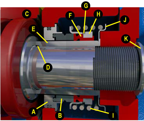
2. Prepare the stationary seal seat, Item A, by applying a thin coat of oil to the o-ring mounted on the outside diameter of the stationary seal seat. Remove the stationary seal face, Item B, from the stationary seal seat.
3. Press the stationary seal seat into the seal plate, Item B, with the stationary seal face o-ring facing the impeller. Turn the seal plate over and inspect the stationary seal seat to ensure that it is completely install and square in the stationary seal seat bore.
4. Install the stationary seal face, Item C, into to
stationary seal seat with the chamfer on the outside diameter facing you. Clean the stationary seal face with a clean, lint free cloth. The faces can be cleaned
with electrical contact cleaner.
5. If required by your pump model, install the o-ring, Item D, onto the shaft.
6. Install the seal plate onto the bearing housing.
7. If your pump utilizes a shaft sleeve, Item E, install the cage and bellows assembly, Item F, onto the shaft sleeve. Do this by placing the sleeve with the chamfered or undercut end within the inside diameter of the sleeve on a flat surface. With the flange of the cage facing downward, firmly press the cage and bellows assembly onto the sleeve until the flange of the cage contacts the surface. Contacting the surface ensures that the cage flange is perpendicular to the sleeve. The chamfered or counter bored inside diameter end of the sleeve is installed onto the shaft first and accommodates the inside radius of the pump shaft. The counter bored inside diameter end of a sleeve usually accommodates an o-ring to seal between the sleeve and the shaft. If a lubricant is required to ease the installation of the cage and bellows assembly onto the sleeve, use a light oil on the inside diameter of the bellows. Do not use any lubricant heavier than the SAE 30, non-detergent motor oil that will be used in the pump. Never use Vaseline, Never-Seize, grease, or a super lubricant such as silicone or STP. The idea of the lubricant is to facilitate the installation of the cage and bellows assembly onto the sleeve only. Too much or the wrong kind of lubricant will cause the bellows spin on the sleeve. The bellows of the seal is supplied with a vulcanizing compound on the inside diameter. Once installed, the pressure of the drive band, Item G, mounted in the cage and bellows assembly causes the bellows to adhere to the sleeve. If this adhesion does not occur, the rotating portion of the seal assembly will rotate at a different speed than the pump, causing excessive wear to the bellows and cage.
8. Install the rotating seal face, Item H, into the cage and bellows with the flat side against the bellows and the chamfer facing you. Clean the rotating seal face using an electrical contact cleaner and a lint free cloth.
9. Slide the sleeve, including the cage and bellows assembly and the rotating seal face, onto the shaft with the seal face facing the stationary seal seat until the seal faces contact one another.
10. Using a second sleeve or a set of screwdrivers, push the sleeve through the bellows until it bottoms against the shaft shoulder.
11. Install the spring, spring centering washer, and the proper amount of shims, Items I, J and K, to achieve the proper seal plate to impeller clearance.
12. Install the impeller and secure.
13. The mechanical seal is lubricated with SAE 30, non-detergent motor oil. Fill the seal cavity to the proper level on the oil cup or within the seal cavity.
Always review the pump’s operation and maintenance manual prior to performing any maintenance or repair. Each seal assembly, regardless of design, is supplied with seal installation instructions. Remove them from the seal container and review them prior to performing any repair.