United States
Canada
- Europe
Netherlands
Germany
- Africa
- Rest of World
Pumps and systems are installed, started, operated, and many times, forgotten. When a problem arises, it’s recommended to install a discharge pressure gauge and suction vacuum gauge on the system. These gauges should be installed near the suction inlet and discharge outlet of the pump. These gauges are usually installed properly, recorded, and along with a pump speed measurement can be plotted on a pump performance curve. This is the beginning of troubleshooting a pump and system.
This data usually leads to the problem and subsequent solution. But, what if the gauges were installed incorrectly? Incorrectly installed gauges may give accurate, but confusing, readings. In Figure 1, gauges have been installed and readings could be taken. To be as precise as possible, the distance in vertical height between the two gauge connections is defined as gauge correction and must be added to the gauge readings to complete total dynamic head. Only then can these readings be transferred to a pump performance curve, beginning the necessary steps to troubleshoot or just document current total dynamic head and flow.
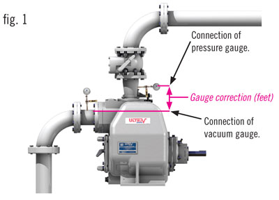
Let’s back up to the pump and system shown in Figure 1. To properly measure the vacuum and pressure, hoses should be installed on the gauges allowing the discharge or pressure gauge to be lowered to the same elevation as the suction or vacuum gauge. This eliminates the need to consider and add to the gauge readings a gauge correction factor. One consideration must be made when hoses are used. Hoses have the ability to retain water, air, or a mixture of both. If a vacuum gauge hose retains water and can not drain during operation, the gauge reading on its dial will change as the elevation of that gauge varies (See Figure 2).
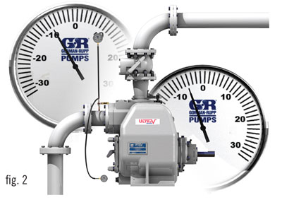
To ensure an accurate reading with an accurate gauge, briefly bleed air into the suction piping through a bleed valve while the pump is operating (See Figure 3). Any trapped liquid within the hose will be pulled through the hose. The gauge will then read accurately and measure the vacuum within the suction pipe where the connection of the vacuum gauge/hose is made. With the hose evacuated of all product, the vacuum reading will remain the same with the gauge at any elevation. Thus, the point or elevation of the vacuum reading taken is the point of attachment to the suction pipe.
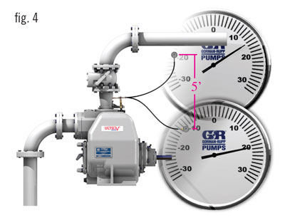
Because the pressure gauge needs fluid pressure at the gauge to measure accurately, a like bleed valve arrangement is required to evacuate the air from the hose. Unlike the vacuum gauge hose, the pressure will change on the dial as elevation varies (See Figure 4). Therefore, the pressure gauge should be held at the same elevation as the vacuum gauge connection point. No gauge correction would be necessary. If for whatever reason, the pressure gauge can not be located at the same elevation as the vacuum gauge connection, then add the vertical distance back to the vacuum gauge connection when the pressure gauge is located higher than the vacuum gauge connection (See Figure 5). Conversely, subtract the vertical distance back to the vacuum gauge connection when the pressure gauge is located lower than the vacuum gauge connection.

In conclusion, make sure that the gauges used to measure pressure and vacuum are quality, liquid filled gauges and the internal pressure within those gauges is equalized to atmospheric pressure before taking any readings. Results from atmospheric pressure changes on gauges will pre-record a reading on its dial. Always remember to check for zero readings before starting.